Molecular Orbitals and Covalent Bonding
Molecular orbitals are formed when two atomic orbitals overlap, resulting in a new orbital with lower energy. This overlap is fundamental to the formation of covalent bonds. There are two primary types of covalent bonds based on the nature of this overlap: sigma (σ) bonds and pi (π) bonds.
Sigma (σ) Bonds
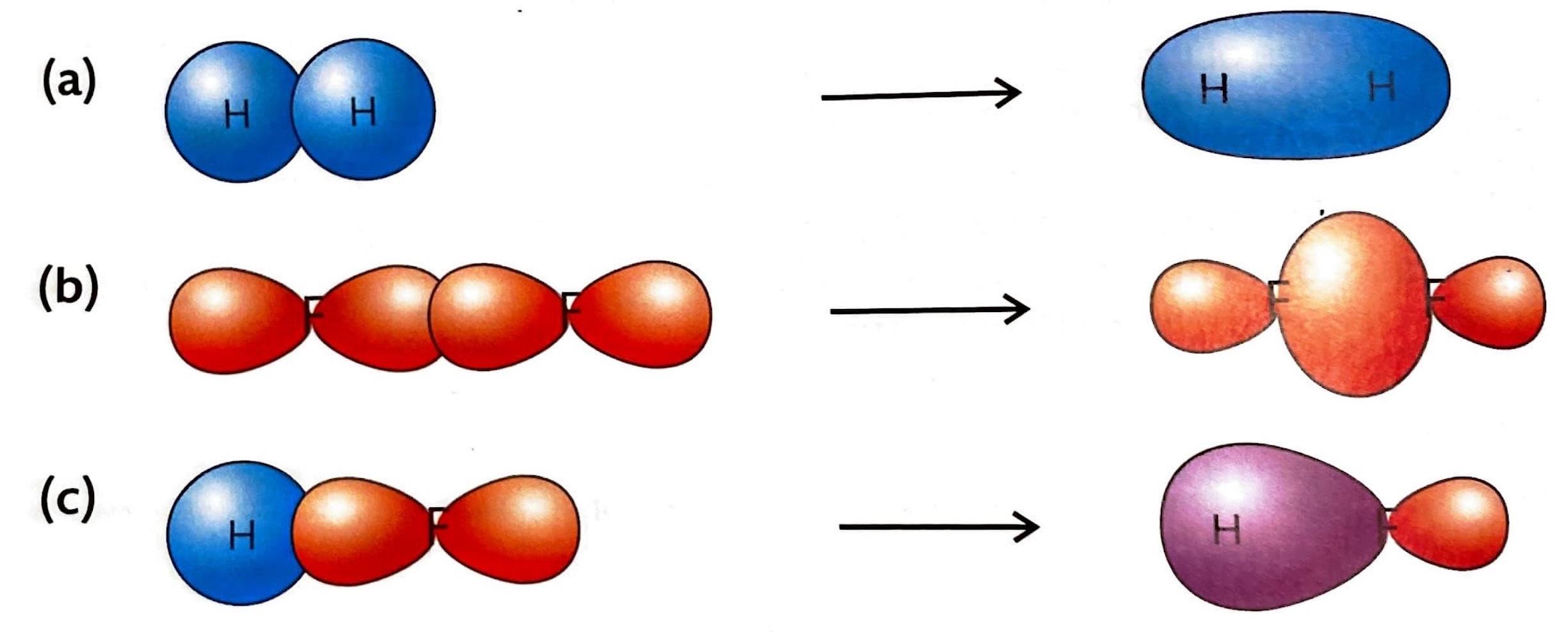
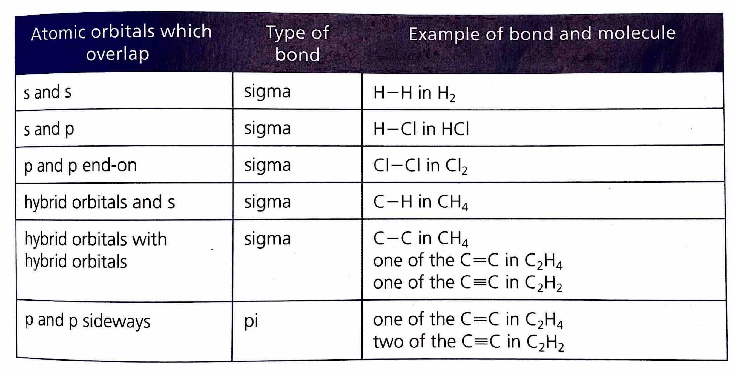
A sigma (σ) bond is the type of bond that forms in every single covalent bond. It is characterized by the direct, head-on overlap of atomic orbitals. This overlap can occur between s orbitals, p orbitals, or hybrid orbitals in various combinations. The electron density in a sigma bond is concentrated directly between the nuclei of the bonded atoms, along the internuclear axis.
Pi (π) Bonds
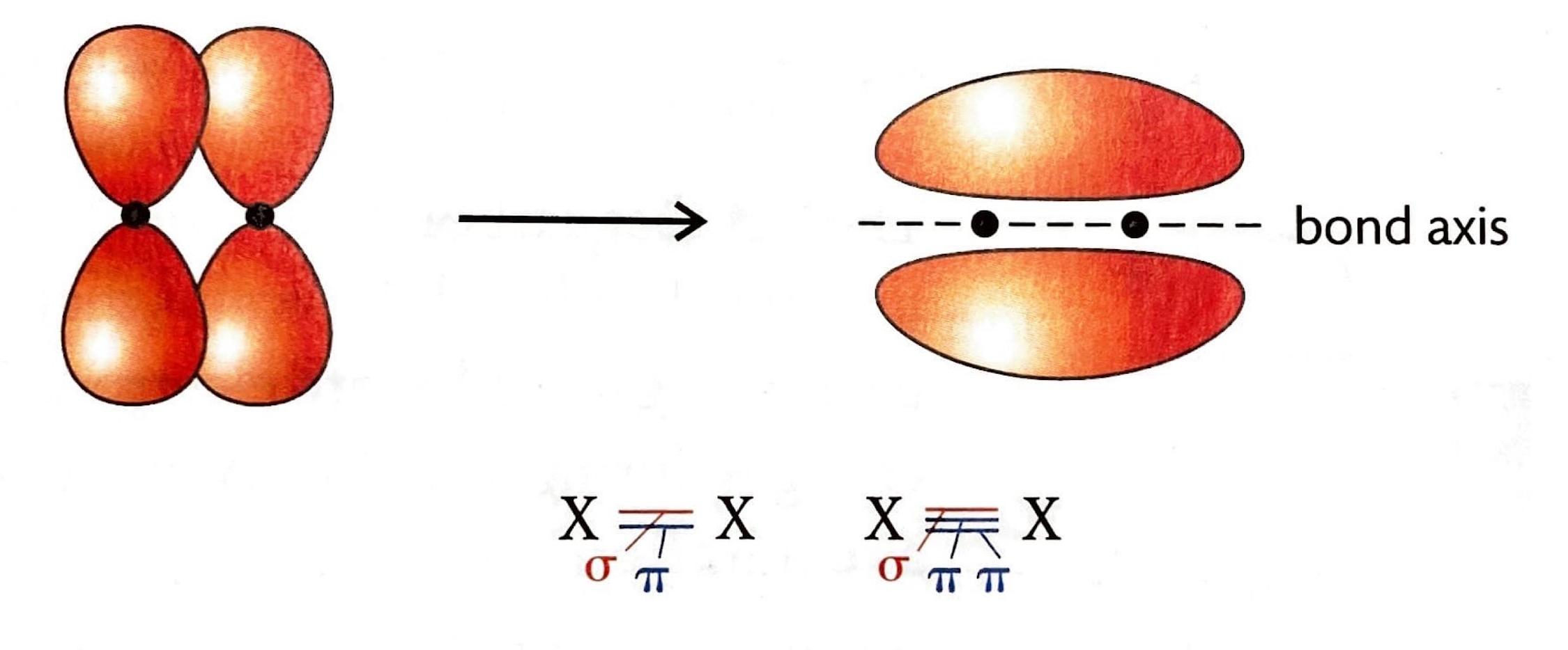
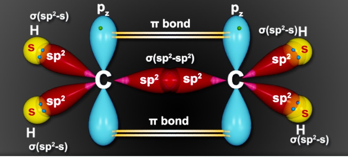
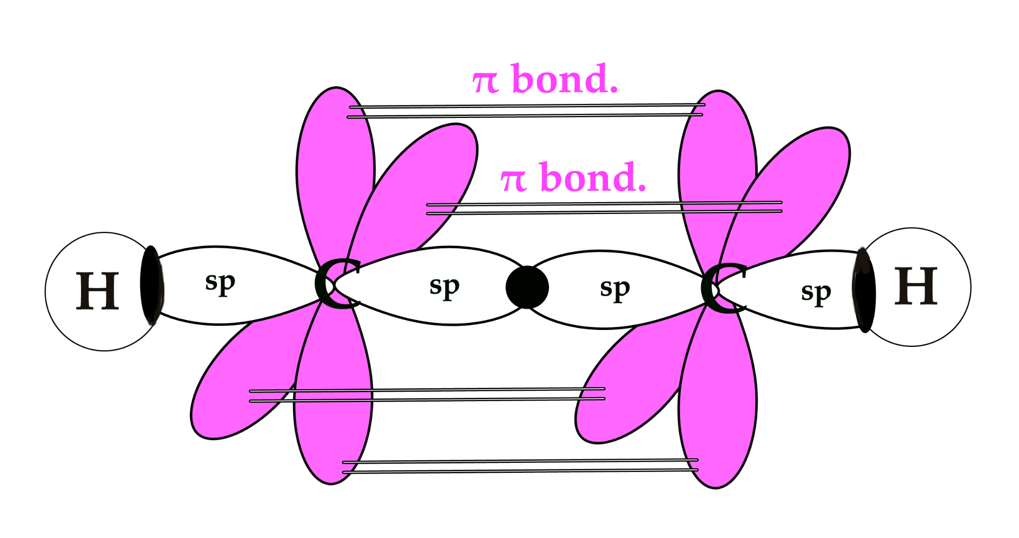
Pi (π) bonds are formed in addition to a sigma bond within double or triple covalent bonds. They arise from the sideways overlap of unhybridized p orbitals. In a pi bond, the electron density is concentrated above and below the plane of the bond axis, rather than directly between the nuclei.
Introduction to Hybridization
Hybridization is a theoretical concept used to explain the observed geometries of molecules. It is the process where atomic orbitals within an atom mix to produce new, degenerate hybrid orbitals that have intermediate energy and different shapes compared to the original atomic orbitals. These hybrid orbitals are more effective at forming stronger covalent bonds because they allow for greater overlap with other atomic orbitals.
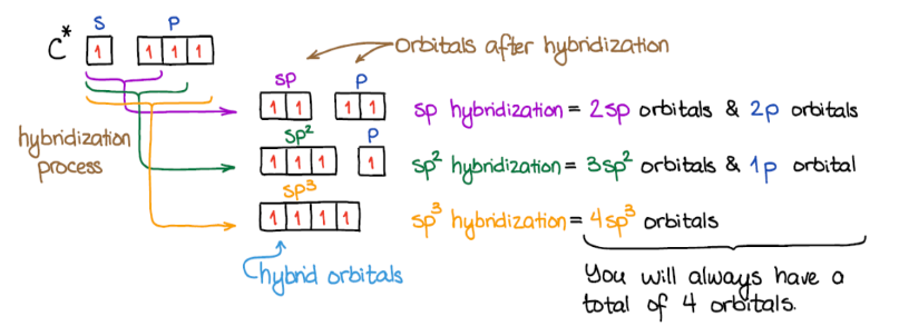
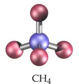
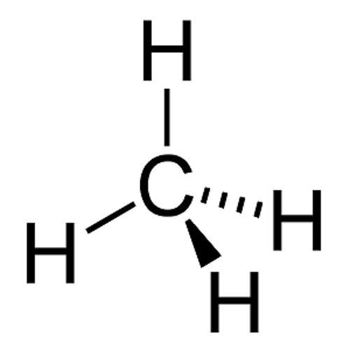
sp3 Hybridization
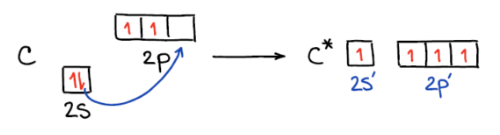
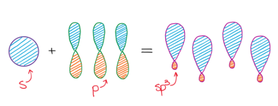
In sp
3 hybridization, one 2s atomic orbital and three 2p atomic orbitals combine to form four equivalent sp
3 hybrid orbitals. This process often involves the conceptual promotion of an electron from the ground state 2s orbital to a 2p orbital, making four orbitals available for mixing. The resulting sp
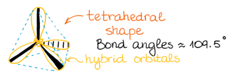
3 hybrid orbitals are oriented in a tetrahedral arrangement around the central atom, leading to a tetrahedral molecular geometry.
It is important to remember that the number of hybrid orbitals produced always equals the number of atomic orbitals that mix. For instance, mixing four atomic orbitals (one s and three p) will always yield four hybrid orbitals.
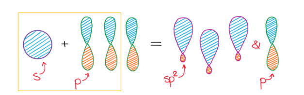
sp2 Hybridization
sp
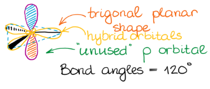
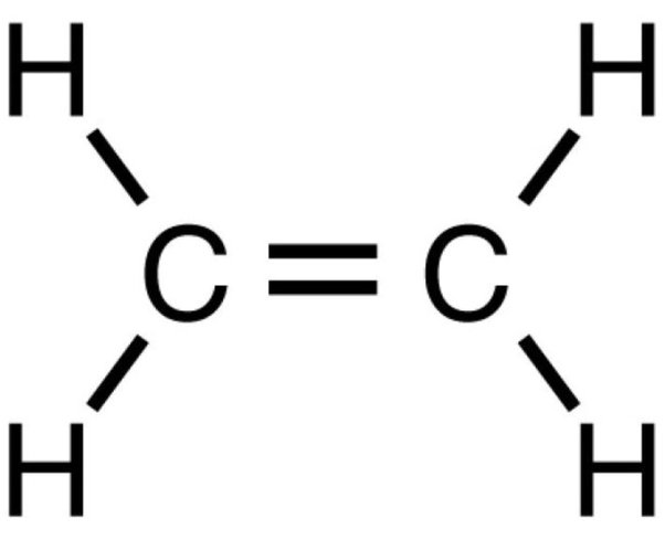
2 hybridization involves the mixing of one s atomic orbital and two p atomic orbitals to form three equivalent sp
2 hybrid orbitals. These three sp
2 hybrid orbitals lie in a plane and are oriented 120° apart, leading to a trigonal planar electron domain geometry. The remaining unhybridized p orbital is perpendicular to this plane and can participate in the formation of a pi (π) bond through sideways overlap with another unhybridized p orbital on an adjacent atom.
sp Hybridization
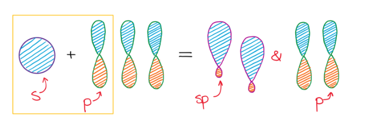
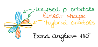
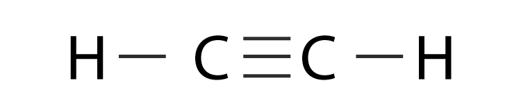
sp hybridization occurs when one s atomic orbital and one p atomic orbital mix to form two equivalent sp hybrid orbitals. These two sp hybrid orbitals are oriented 180° apart, resulting in a linear electron domain geometry. The two remaining unhybridized p orbitals are perpendicular to each other and to the sp hybrid orbitals. These unhybridized p orbitals can participate in the formation of two pi (π) bonds, typically found in triple bonds, through sideways overlap.
Electron Groups and Hybridization
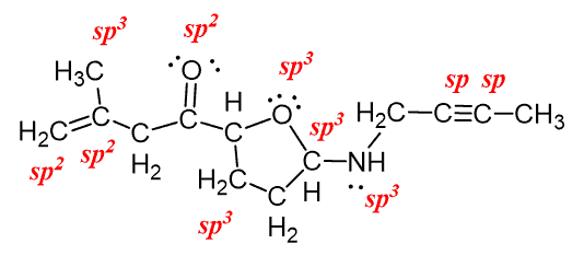
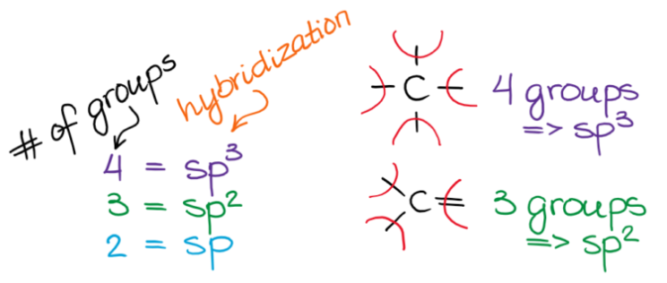
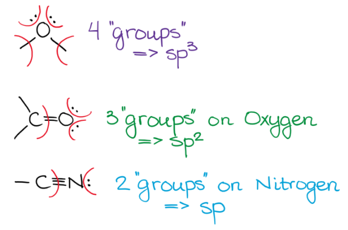
The concept of an "electron group" is crucial for determining hybridization and molecular geometry. An electron group can be defined as any of the following: a lone pair of electrons, a single bond, a double bond, or a triple bond. The number of electron groups around a central atom dictates the hybridization state of that atom.
Predicting Molecular Shape with Hybridization
Hybridization is a powerful tool for predicting the electron domain geometry and, consequently, the molecular geometry of a molecule. The number of electron domains around a central atom directly corresponds to its hybridization state and the resulting spatial arrangement of those electron domains. The table below summarizes the relationship between the number of electron domains, electron domain geometry, molecular geometry, and hybridization, along with illustrative examples.
| Number of electron domains |
Electron domain geometry |
Molecular geometry |
Example |
Hybridization |
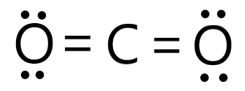
| 2 |
linear |
linear |
CO2 |
sp |
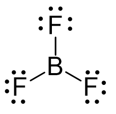
| 3 |
trigonal planar |
trigonal planar |
BF3 |
sp2 |
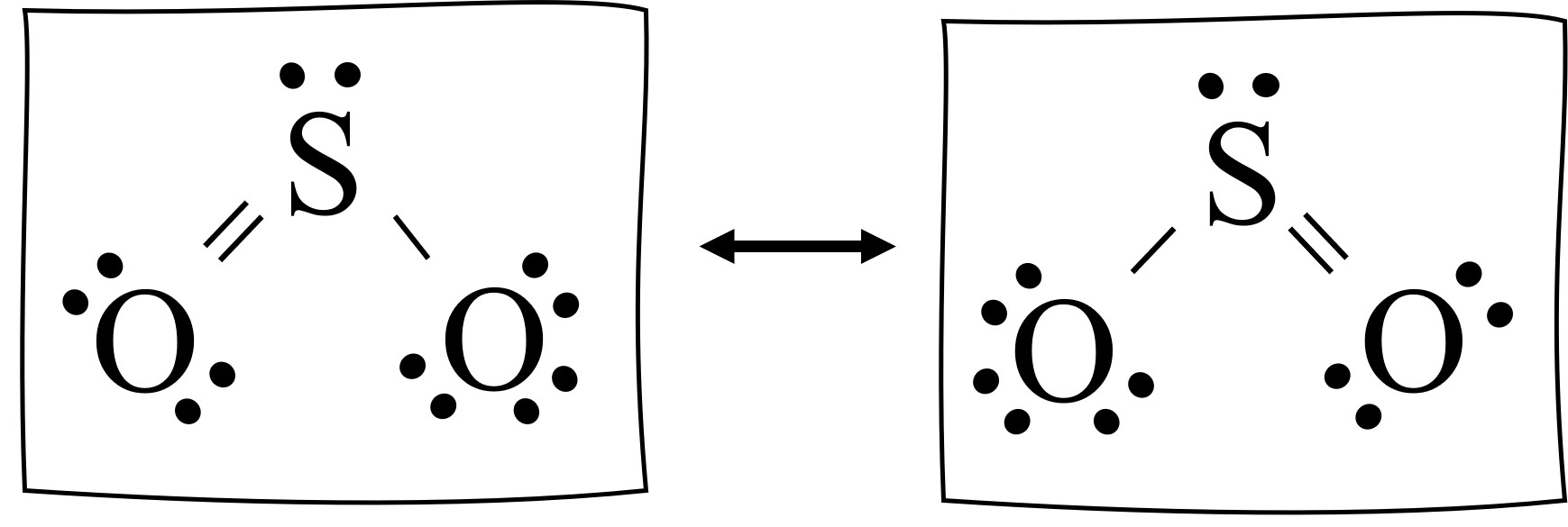
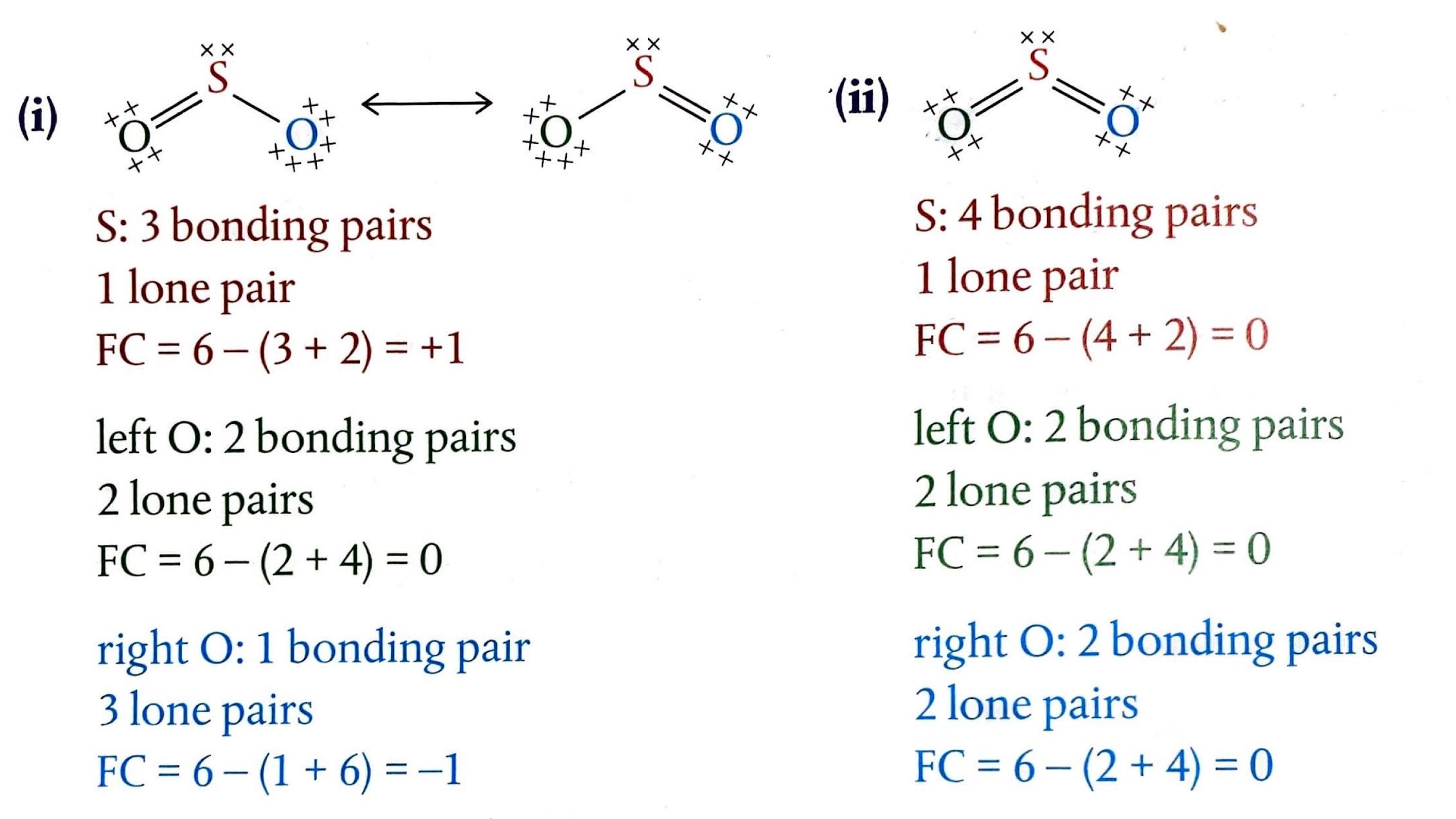
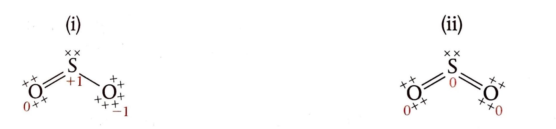
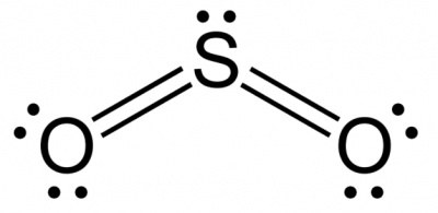
| 3 |
trigonal planar |
bent |
SO2 |
sp2 |
| 4 |
tetrahedral |
tetrahedral |
CH4 |
sp3 |
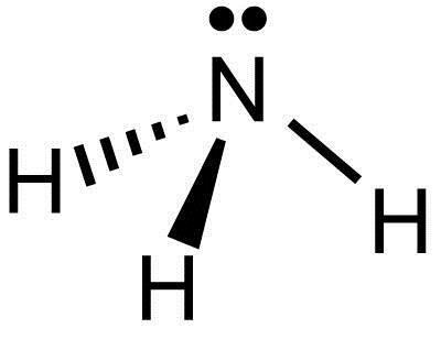
| 4 |
tetrahedral |
trigonal pyramidal |
NH3 |
sp3 |
| 4 |
tetrahedral |
bent |
H2O |
sp3 |